4. 3D printing process
3D printing is any of various processes in which material is joined or solidified under computer control to create a three-dimensional object.
Starting with 3D modelling it is possible to create an accurate reproduction of the final product using model automatic production system such CAM (Computer-Aided Manufacturing) which is made up of “Numerical Control Machine” or “Rapid Prototyping”.
Computer numerical control (CNC) or simply numerical control (NC) is the automated control of machining tools (drills, boring tools, lathes) by means of a computer, in which an NC machine operates on a piece of material (metal, plastic, wood, ceramic, or composite) to transform it into precise specifications.[1] It is a process that works by subtraction of material.
“Rapid prototyping is a group of techniques used to quickly fabricate a scale model of a physical part or assembly using three-dimensional computer-aided design (CAD) data. Construction of the part or assembly is usually done using 3D printing or “additive layer manufacturing” technology.[2] So it is the opposite process as it acts by adding material.
Rapid Prototyping is the most popular technique at this moment, for the low costs and for an unnecessary high awareness of the technical aspects of the printing process.
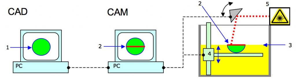
Image 4.1 [source]
For more information on 3D printing and printers, refer to Module 1: “Introduction to digital prototyping tech”.
Anyway, it is useful to summarize briefly a typical printing process:
Once the digital 3d model is generated:
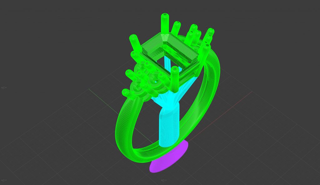
Image 4.2
the steps of rapid prototyping are:
1. Creating the .STL file:
It is a preliminary phase to the actual prototyping and consists in the generation of the .STL file and in its verification. The .STL (Standard Triangulation Language To Layer) file is a graphical standard that describes the object by means of a triangulation decomposition of the surfaces that compose it. In practice, the surfaces of the piece are meshed with triangular elements. Approximately increasing the number of triangles improves the definition of the surface
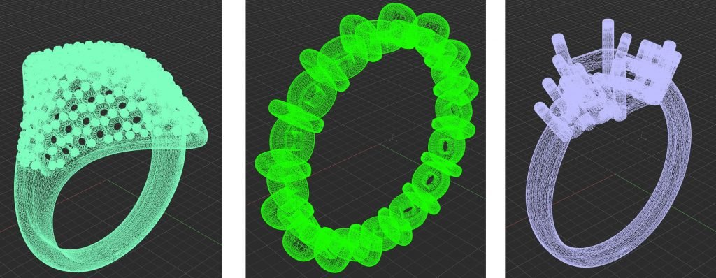
Image 4.3
2. Management of the .STL file:
Once the STL file has been generated, it must be verified that it is free of errors. Once this verification has been carried out, it is possible to perform slicing, ie to generate the “slices” that are placed one on top of the other and give life to the final solid. Slicing is a critical operation because it determines the surface characteristics of the finished object. This operation can be either uniform or adaptive when the thickness of the slices is variable and is chosen according to the curvature of the surface in order to better adapt the final geometry, reducing the staircase effect (the inclined surfaces are approximate from steps).
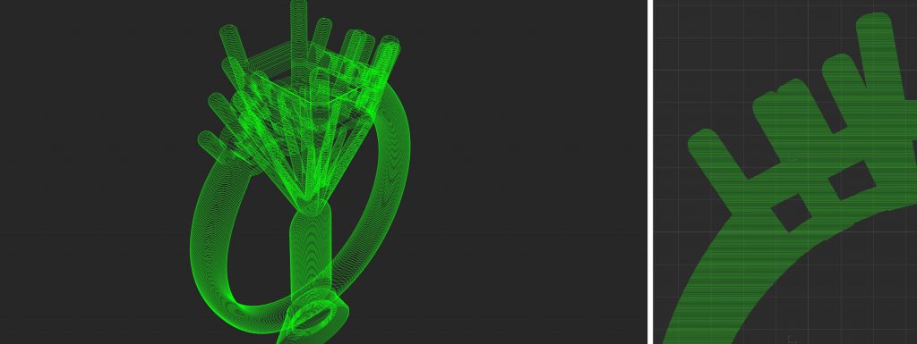
Image 4.4
3. Printing: Construction of the “layer by layer” prototype:
It consists of sending the STL file or the slices, depending on the prototyping model, to the machine and proceeding with the deposition of the material layer by layer until reaching the final object.

Image 4.5. Schematic representation of Stereolithography: a light-emitting device a) (a laser or DLP) selectively illuminates the transparent bottom c) of a tank b) filled with a liquid photo-polymerizing resin. The solidified resin d) is progressively dragged up by a lifting platform e)[3]
4. Post treatments
These are manual operations whose purpose is to remove the object from the machine and clean it from the excess material. As you can see from the process just described, in the management of the printing phase it is not necessary to have a high knowledge of the technical aspects of 3D printing as the process is almost entirely managed by the machines.
As for the use of 3D modeling also the use of 3D printing involves a number of advantages in the production phase.
They can be summarized in:
- – reduction of time in prototype relocation
- – reduction of costs
- – the possibility of screening alternative solutions
- – ease of verification of the actual dimensions
- – increase in the prediction of error
- – modification during construction
- – different materials
- – eco-sustainability due to the reduction of waste in the construction of prototypes
- – easy communication with the use of real objects
References:
[1] https://en.wikipedia.org/wiki/Numerical_control
[2] https://en.wikipedia.org/wiki/Rapid_prototyping
[3] https://en.wikipedia.org/wiki/Stereolithography