5. First steps in 3D printing – 2D-3D transformations
Another way of introducing 3D printing and practicing TinkerCAD is by creating 3D models from 2-dimensional graphics. For this purpose you can use almost every graphic you find in the real and virtual world (of course not all of them will work just as good as the others). You can also draw something by yourself, scan or photograph it and then turn into a 3D model which can be printed in three dimensions.
One of the possible scenarios could look like this:
1. Draw or write something on paper and then take a photo of it (your smartphone is good enough for this, but you can use also more advanced equipment):
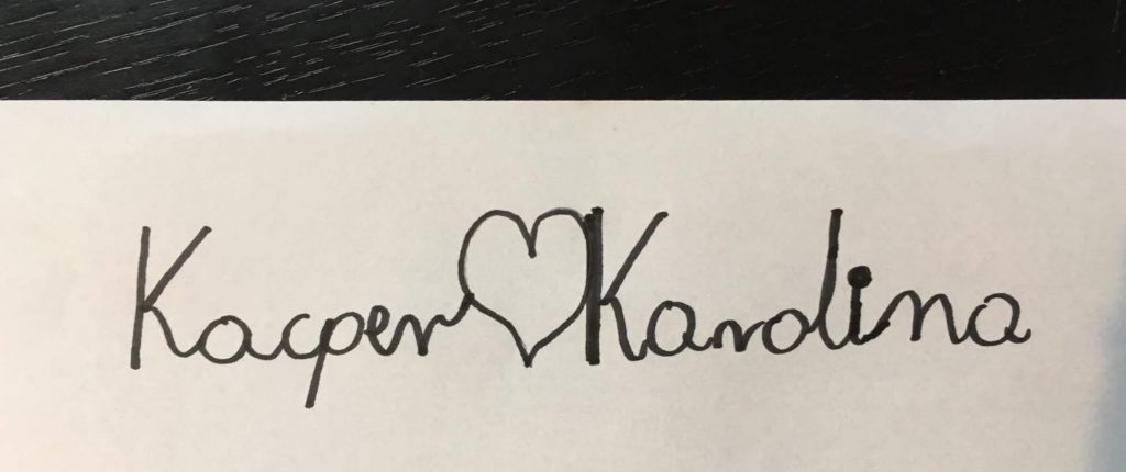
Image 5.1
2. Now you have to remove the background and all the other elements which aren’t a part of a shape which you are going to print later. Remember that even shadows or seemingly meaningless dots may later become real shapes in your project.
One of the programmes which can be used for “clearing” the picture is Paint 3D – an app available for free for the users of Windows 10. One of its functions is “Magic Select”. The programme is very intuitive and guides you step by step through the process. Thanks to it you will be able to select and crop only the elements you need for your model. The selected and cropped content you paste to the new document and save as .png file without background.
3. Your project is almost ready. However, TinkerCAD supports only a limited number of graphical formats (.stl, .obj and .svg), which, in turn, are not supported by Paint 3D. Luckily there’s an easy way of changing the format from one to another; in this case from .png to .svg.
Besides professional programmes for graphic edition, there’s a number of free online converters, which you can use. We recommend https://image.online-convert.com as it has never failed so far. The procedure is easy. You open the website, upload the file, click “Start conversion” and download the file which appears in the window.
4. The .svg file is ready to upload to TinkerCAD.
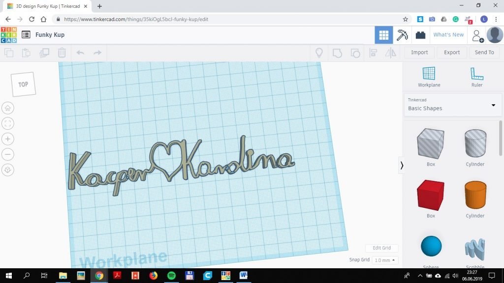
Image 5.2
In this case, we can use ThinkerCAD for customising the shape or just providing some improvements, which will make the shape more stable.
Here, for instance, we had to add small supporting elements between and inside the letters. Without them, the words were too weak and fell apart.
Some of the supports you can see in this picture:

Image 5.3
And here there’s the printout made before this improvement:
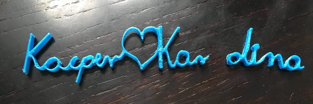
Image 5.4
Luckily the author decided to connect the dot over the “i” from the beginning. Otherwise, it would be necessary to work on it as well.
Finally, after all the corrections, use Cura Ultimaker to prepare the .gcode for the printer and print your shape:
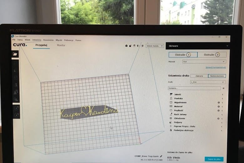
Image 5.5

Image 5.6