9. 3D Printers – FDM 3D printing
In FDM, an object is built by selectively depositing melted material in a pre-determined path layer-by-layer. The materials used are thermoplastic polymers and come in a filament form.
A designer should keep in mind the capabilities and limitations of the technology when fabricating a part with FDM, as this will help him achieve the best result.
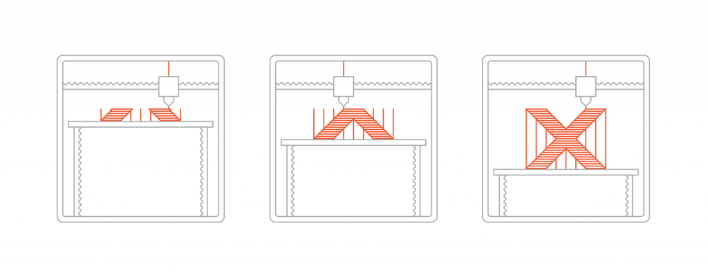 Image 9.1. The FDM printing process [source]
Here is how the FDM fabrication process works:
1. A spool of thermoplastic filament is first loaded into the printer. Once the nozzle has reached the desired temperature, the filament is fed to the extrusion head and in the nozzle where it melts.
2. The extrusion head is attached to a 3-axis system that allows it to move in the X, Y and Z directions. The melted material is extruded in thin strands and is deposited layer-by-layer in predetermined locations, where it cools and solidifies. Sometimes the cooling of the material is accelerated through the use of cooling fans attached on the extrusion head.
3. To fill an area, multiple passes are required (similar to coloring a rectangle with a marker). When a layer is finished, the build platform moves down (or in other machine setups, the extrusion head moves up) and a new layer is deposited. This process is repeated until the part is complete.
What is important from a designer’s perspective is to build size and layer height:
The available build size of a desktop 3D printer is commonly 200 x 200 x 200 mm, while for industrial machines this can be as big as 1000 x 1000 x 1000 mm. If a desktop machine is preferred (for example for reducing the cost) a big model can be broken into smaller parts and then assembled.
The typical layer height used in FDM varies between 50 and 400 microns and can be determined upon placing an order. A smaller layer height produces smoother parts and captures curved geometries more accurately, while a larger height produces parts faster and at a lower cost. A layer height of 200 microns is most commonly used.
Good adhesion between the deposited layers is very important for an FDM part. When the molten thermoplastic is extruded through the nozzle, it is pressed against the previous layer. The high temperature and the pressure re-melts the surface of the previous layer and enables the bonding of the new layer with the previously printed part.
Furthermore, support structure is essential for creating geometries with overhangs in FDM. Support is usually printed in the same material as the part. Support materials that dissolve in liquid also exist, but they are used mainly in high-end desktop or industrial FDM 3D printers.
FDM parts are usually not printed solid to reduce the print time and save material. Instead, the outer perimeter is traced using several passes, called the shell, and the interior is filled with an internal, low-density structure, called the infill.
Infill and shell thickness affect greatly the strength of a part. For desktop FDM printers, the default setting is 25% infill density and 1 mm shell thickness, which is a good compromise between strength and speed for quick prints.
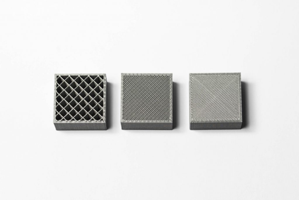
Image 9.2. The internal geometry of FDM prints with different infill density [source]
For more information on the FDM printing technology, you can watch the following video:
Sources:
[1] https://www.3dhubs.com/knowledge-base/introduction-fdm-3d-printing